When a squaring line project moves from concept to layout, the centering and transfer functions are often described loosely as “getting the tile into position.” That description hides two separate engineering questions: what state must the tile be in before the next process can work correctly, and who is responsible for delivering that state across each equipment boundary. A project team that cannot answer both questions for every handoff will struggle to compare supplier proposals on equal terms, because each supplier may be solving a different problem without saying so.
Define Each Handoff by the Tile State It Must Deliver
A handoff is not a piece of equipment; it is a boundary condition. The useful way to define it is by the tile state that must exist on each side of that boundary, not by naming a machine or a mechanism. This distinction matters because two lines can use different equipment arrangements and still satisfy the same handoff if the incoming and outgoing states are equivalent. Conversely, two lines can use the same equipment category and fail to interoperate if the states they assume are different.
Where a project defines a handoff by function alone, without specifying design, the buyer keeps room to compare different supplier approaches on equal footing. Functional requirements — describing what a system must do rather than prescribing how it must be built — are the basis GOV.UK guidance on technical specifications supports for exactly this reason: they let requirements be shared and compared without locking in an unproven design early. Applied to a squaring line, this means stating what position, orientation, spacing, support, and edge or surface condition the tile must have when it leaves one function and arrives at the next, rather than assuming a particular conveyor type or centering mechanism will produce that state.
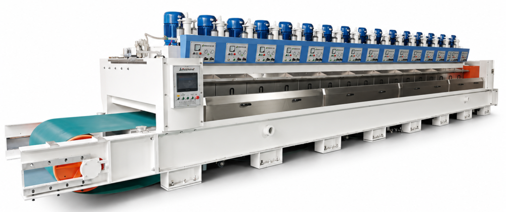
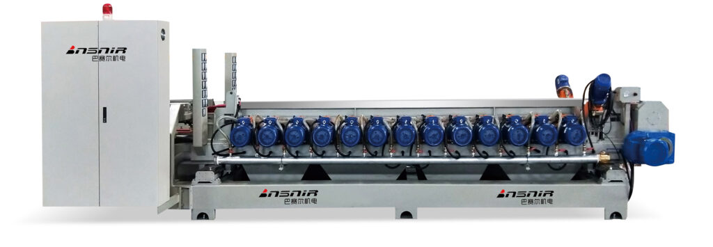
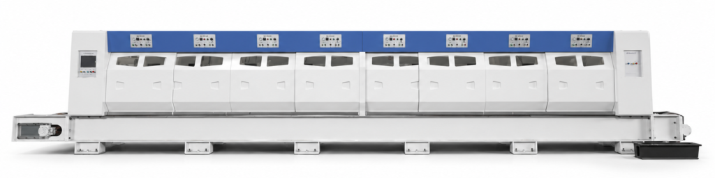
This state description also has to include production context, because a tile state that is acceptable at one line speed or one format range may not be acceptable at another. A handoff defined only in geometric terms, without reference to how it performs across the production conditions the project intends to run, is incomplete. The categories a current ceramic-finishing equipment inventory lists — transfer systems, centring units, squaring, roller tables, dimensional control — show that these are treated as distinguishable responsibilities in current manufacturer practice, which supports separating them conceptually even before any project decides how to combine them physically. That precedent does not define how any specific handoff must behave; it only confirms that treating them as separate questions is a reasonable starting point.
Until values are agreed, each of these state variables should be treated as an open project question rather than a specification. Writing “position tolerance to be confirmed” is more accurate at this stage than adopting a number from an unrelated project or product page.
| Handoff question | Centering responsibility | Transfer responsibility |
|---|---|---|
| What tile state is accepted? | Ask which incoming position, orientation, size, and variation the centering function is expected to accept | Ask which outgoing state from the prior function the transfer must receive |
| What state is delivered? | Define the reference state required by the next squaring or chamfering responsibility | Define which agreed position, orientation, spacing, and support state must be preserved or delivered |
| What may change? | Identify which state the proposed centering function may correct | Identify whether the proposed transfer only preserves state or also performs another agreed function |
| What remains unknown? | Values, correction envelope, hardware, and control logic | Values, conveyor arrangement, interface logic, and allowable disturbance |
Separate Centering Responsibility From Transfer Responsibility
Centering and transfer are frequently combined in the same physical station, and a project may reasonably choose to buy them that way. But combining them physically does not mean they are the same responsibility, and treating them as one can hide where a fault or a design gap actually sits.
Centering, as a function, is what establishes the tile’s reference position for whatever process comes next — the point from which squaring, chamfering, or another downstream operation measures its own action. Transfer, as a function, is what carries the tile from one responsibility to another while preserving whatever state the next step depends on. The distinction is not cosmetic: centering is expected to act on the tile’s position, while transfer is expected, in the general case, to protect a position that has already been set. When a project asks “what corrects the tile’s position” and “what merely carries the tile,” it is asking about two different failure modes, even where a single machine performs both actions.
This separation becomes important when something goes wrong. If a tile arrives at a downstream station out of position, the diagnostic path differs depending on whether the centering function failed to establish the reference correctly or the transfer function disturbed a reference that had been established correctly upstream. Without a clear boundary between the two responsibilities, a project has no way to assign that fault, and a supplier proposal that bundles both functions into one undivided description leaves the same ambiguity unresolved.
The manufacturer precedent of listing centring units and transfer systems as separate equipment categories supports treating them as distinct responsibilities even in a combined physical design; it does not establish what either function can actually correct in a given project, or how much disturbance a transfer step may introduce without affecting the next process. Those are properties of the specific equipment and configuration proposed, not of the general category.
The useful questions for a project team are: what state can the proposed centering function actually correct, and within what range; what does the proposed transfer function only preserve, and where does its responsibility end; and at the boundary between the two, who is accountable if the tile arrives in the wrong state. Where a supplier proposes a single integrated station, the project should still expect these questions to have separate answers, because the answers determine what commissioning or trial evidence needs to demonstrate later.
Map Upstream and Downstream Interface Ownership
Every centering and transfer handoff sits inside a larger constraint: the existing factory layout, the equipment already on either side of the new line section, and whatever mechanical, electrical, and control connections join them. A functional description of a handoff is necessary but not sufficient; the project also needs to know who owns each piece of that connection before proposals can be compared meaningfully.
HSE’s guidance on buying new machinery supports discussing requirements directly with potential suppliers, particularly where equipment is complex or custom-built, and considering where and how it will actually be used. Applied here, this means the project team should not assume a supplier’s standard interface logic will match an existing factory’s layout, utility routing, or upstream and downstream equipment without that discussion taking place explicitly. A proposal that looks complete on paper can still leave interface ownership unstated, and an unstated ownership gap tends to surface only once installation begins.
The practical approach is to work through each boundary and ask four things: who supplies the incoming tile-state data, who defines the target state on the far side, who owns the mechanical, electrical, and control integration at that specific joint, and who is responsible for recording that the handoff was verified. These four answers will differ depending on whether the boundary sits inside a single supplier’s scope or crosses between two different suppliers, or between a supplier and the existing factory installation.
This is also where existing-factory constraints need to be kept separate from supplier-proposed architecture. A factory’s fixed space, utility supply, or upstream equipment is a constraint the project must describe accurately; a supplier’s proposed interface design is a response to that constraint, not a substitute for it. Conflating the two makes it hard to tell whether a proposal is genuinely compatible with the factory or simply describes an idealized installation. GOV.UK’s guidance on sharing a common description of requirements supports keeping these as separate, explicit statements rather than letting one supplier’s assumptions stand in for the project’s actual conditions.
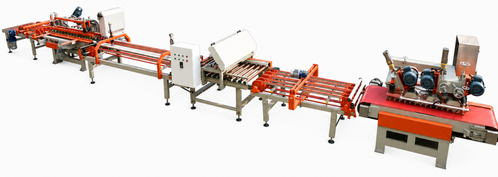
Where a project is evaluating equipment such as a squaring and chamfering machine line as part of this interface map, the ownership questions above apply at each boundary that line touches, both upstream of centering and downstream of transfer, regardless of which supplier’s scope eventually covers which side.
| Interface item | Buyer must provide or decide | Supplier must explain | Joint confirmation |
|---|---|---|---|
| Incoming tile state | Actual tile envelope and upstream condition | Accepted input assumptions | Any exclusions and data gaps |
| Required outgoing state | State needed by the next process responsibility | How the proposal intends to deliver it | Evaluation basis and evidence |
| Existing factory boundary | Fixed space, utility, and upstream/downstream constraints | Proposed mechanical, electrical, and control interfaces | Responsibility at each connection |
| Verification record | Required decision and record users | Proposed measurement or observation method | Trial conditions, sample scope, and sign-off route |
Turn Handoff Requirements Into Reviewable Evidence
Once a handoff is defined by tile state and its ownership is mapped across the relevant boundary, the project still needs a way to check that a supplier’s proposal actually satisfies it. A functional requirement without an evidence request is not verifiable; it is simply a hope stated in careful language.
GOV.UK’s guidance on technical specifications supports linking requirements to evidence, and that link is what turns a handoff description into something a project team can actually review before committing to a proposal. Practically, this means asking for an interface drawing or an equivalent written state description for each handoff, the tile-envelope assumptions the proposal is built on, a proposed method for verifying the handoff, and records showing the handoff performed under agreed trial conditions.
Each of these evidence elements answers a narrow question, and none of them should be read as answering a broader one. A drawing shows that both sides understand the boundary the same way; it does not show that the boundary performs as intended. A stated tile-envelope assumption shows what conditions the proposal claims to cover; any condition outside that assumption remains unconfirmed, whatever the rest of the proposal implies. A verification method shows how the handoff can be checked, not what the specific pass or fail values should be — those still require project agreement. A trial record shows what was observed for the conditions actually tested; it does not extend to conditions, formats, or speeds that were not part of that trial.
This boundary matters most at the point where a project is tempted to read a single successful trial as proof of full-line behavior. Evidence tied to one handoff, tested under one set of conditions, supports a conclusion about that handoff under those conditions and nothing wider. Where a project needs confidence across a broader range of formats or speeds, that confidence needs its own evidence, gathered under those conditions, rather than being inferred from a narrower result.
Where BASAIR or another supplier is asked to configure equipment for a specific handoff, the tile-envelope assumptions, verification method, and trial conditions the project supplies become the basis that proposal is built and reviewed against — which is also why vague or incomplete input at this stage tends to produce a correspondingly vague evidence package back.
| Evidence element | Decision it supports | Boundary |
|---|---|---|
| Interface drawing or state description | Whether the proposed boundaries are understood consistently | Not proof of performance by itself |
| Tile-envelope assumptions | Whether the proposal covers the stated incoming conditions | Unlisted conditions remain unconfirmed |
| Proposed verification method | Whether the handoff can be checked under agreed conditions | Values and pass/fail rules require agreement |
| Trial record tied to conditions | What was observed for the tested handoff | Does not prove full-line or full-range performance |
Frequently Asked Questions
Q: If centering and transfer are supplied together, do we still need separate requirements for them?
A: Yes. Review centering as establishing the agreed tile reference and transfer as carrying the tile while delivering or preserving the state needed next. Ask what each function may correct, what it only preserves, and where its responsibility ends even if both occupy one equipment arrangement.
Q: How can we define a handoff before selecting conveyors or control hardware?
A: Describe the incoming tile state and the state required by the next function. Raise position, orientation, spacing, support, tile condition, and production context as project questions, then ask the supplier to propose the architecture and confirm the applicable values and assumptions.
Q: What should we settle where the new line meets existing factory equipment?
A: Settle the accepted incoming state, required outgoing state, and responsibility for mechanical, electrical, and control integration. Provide the real tile envelope and fixed factory constraints, then confirm who supplies interface data and records verification at each connection.
Q: What evidence lets us review the proposed handoffs without assuming whole-line performance?
A: Request an interface drawing or state description, tile-envelope assumptions, a proposed verification method, and records linked to agreed trial conditions. Assess whether the tested handoff delivered its stated tile state; broader throughput, quality, or acceptance conclusions require their own evidence.