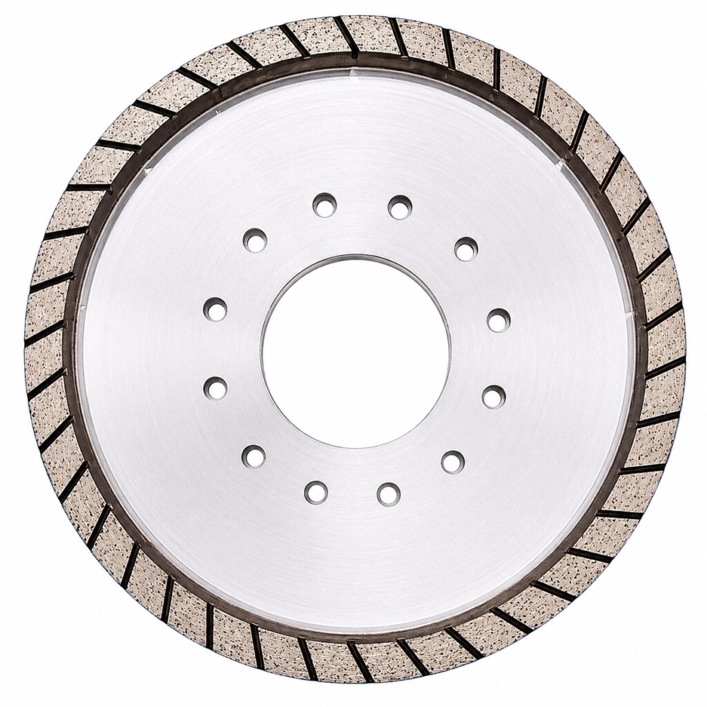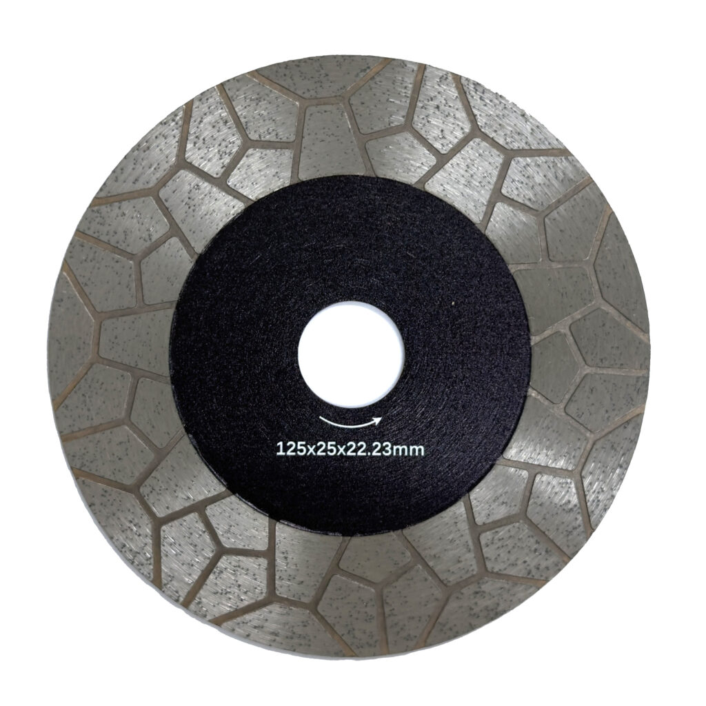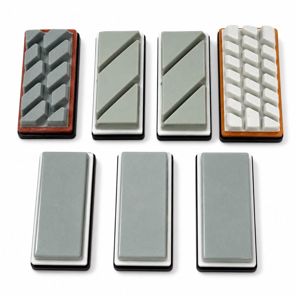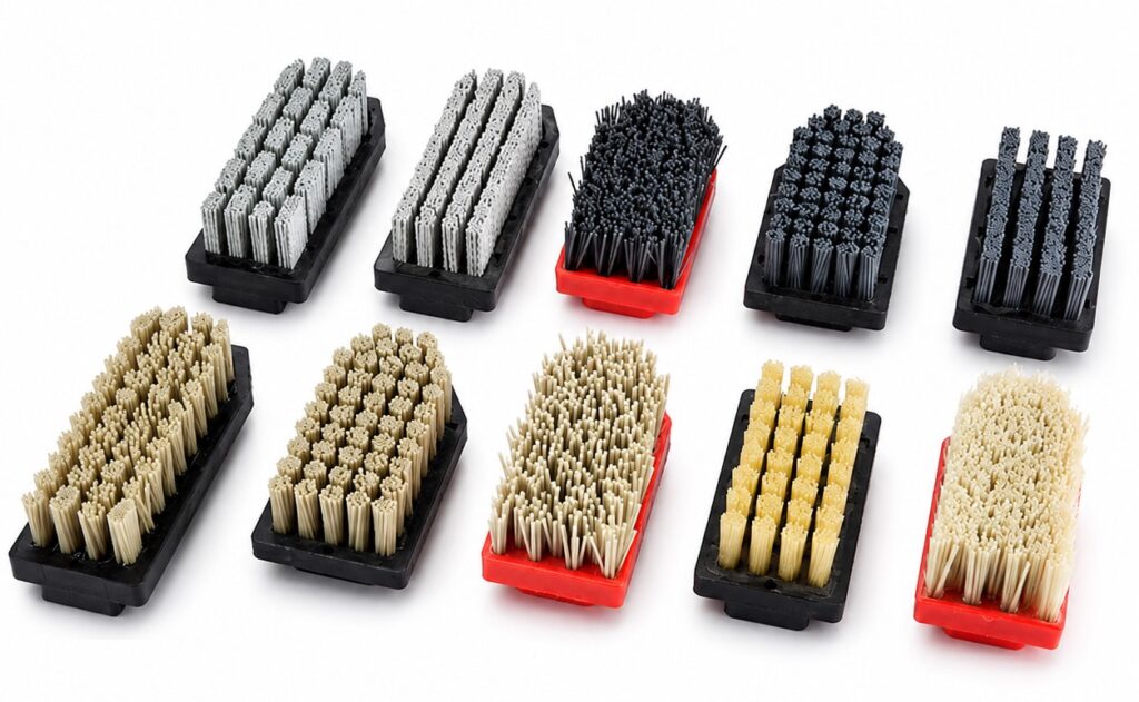
A lappato line that was producing acceptable surface quality last week can start generating visible swirl patterns or repeating arc marks with no obvious change in setup. The instinct in most plants is to swap the final polishing stage first—it is the last thing touching the tile, and the marks are visible on the finished surface. That instinct frequently makes the problem worse: a well-conditioned final abrasive polishing over an upstream scratch can sharpen its contrast and make the tile unsalvageable without revealing anything about where the scratch originated. The decision that resolves most lappato surface-mark problems is not which abrasive to change, but which stage in the line produced the mark and why—and that judgment requires reading the mark geometry before touching any tooling.
Mark Geometry as a Clue to the Source
The shape of a polishing mark is diagnostic information, not cosmetic description. Concentric arcs or full circles on the tile surface point to a Fickert head; curved marks radiating outward from a rotational centre point to a satellite head. These two trajectories are mechanically distinct, and recognising which one is present tells you which part of the line to examine first. Treating all surface marks as equivalent polishing defects and responding with a general abrasive change wastes time and can actively obscure the cause.
The distinction matters most when marks survive to the final stage. If a Fickert-pattern arc is visible after all downstream heads have passed, the trajectory-cancellation mechanism—if present in the line—is failing to erase it, or the pattern is being introduced after cancellation has already occurred. If overlapping or mixed patterns appear on the same tile, the likely issue is inadequate alternation, insufficient head overlap, or dwell-time mismatch between head types.
| Observed Mark Geometry | Likely Head Type | What to Verify |
|---|---|---|
| Concentric arcs or full circles | Fickert head | Head path alignment; if pattern survives later stages, cancellation may be insufficient |
| Curved marks radiating from the centre | Satellite head | Satellite head timing and planetary motion; overlap with Fickert pattern may indicate alternation inadequacy |
| Mixed or overlapping patterns after final stage | Incomplete trajectory cancellation | Fickert‑satellite alternation order, head overlap, and dwell time |
This table works as a starting investigation filter, not a closed diagnostic key. The pattern shapes described come from observed behaviour on a specific alternating-head lappato system, not from a universal defect standard. Before attributing a pattern to a particular head type, verify that the head path geometry on your machine actually produces that trajectory—machines from different manufacturers may configure Fickert and satellite motions differently.
Reading mark geometry correctly determines which stage to investigate; skipping this step means any abrasive change is a guess.
Head Trajectory and Repeating Surface Patterns
A repeating surface pattern after the lappato process is almost always a trajectory problem, not an isolated abrasive problem. When alternating Fickert and satellite heads are used, the design intent is that each head type erases the marks left by the other, because their cutting paths are geometrically perpendicular. Grooves left by a Fickert head’s concentric motion get smoothed by the satellite’s radial sweep, and vice versa. When that cancellation works, the final surface shows neither pattern distinctly.
When it does not work, the pattern that survives to the final surface identifies the head whose marks are not being erased. The operational causes are usually mechanical: the head spacing may not provide sufficient overlap between trajectories, the dwell time at each position may be uneven, or one head type may be cutting more aggressively than the other at a given moment, leaving marks deeper than the subsequent head can remove. Alternating-head cancellation is a design feature of a particular class of lappato equipment; it is not a behaviour shared by all multi-head configurations. If your line does not use an alternating layout, the cancellation logic does not apply, and repeating patterns require a different diagnostic approach based on that line’s actual head sequence and path geometry.
Adjusting head path or alternation order to resolve a repeating pattern is a consequential change. Even when it successfully cancels the original mark, it introduces a new head-path interaction that the line has not been qualified under. Budget for a requalification window before returning to normal production output; teams that skip this step frequently discover a new surface artefact several hours into the next run.
Upstream Scratches Revealed by Later Stages
The final polishing stage of a lappato line does not have enough material removal capacity to eliminate a scratch introduced in an early coarse stage. What it can do is refine the surrounding surface to the point where the scratch becomes more visible against a cleaner background. This is one of the more persistent misdiagnoses in lappato troubleshooting: the defect appears at final inspection, the final abrasive gets changed, and the scratch reappears on the next tiles—sometimes more prominently—because the upstream source was never addressed.
The diagnostic question is not where the mark became visible, but where the surface was first damaged past the removal capacity of subsequent stages. Scratch depth and orientation after each upstream stage are the relevant evidence. A fine scratch line visible after final polishing, oriented in a direction consistent with an early coarse head, suggests the grit sequence did not remove it progressively. A haze or swirl with no clear directional signature more often points to contamination or abrasive glazing introduced at an intermediate stage.
| Defect After Final Polishing | Likely Upstream Source | What to Confirm Before Abrasive Change |
|---|---|---|
| Fine scratch lines still visible | Coarse scratch not removed by intermediate stages | Scratch depth and orientation after each upstream stage; grit sequence integrity |
| Swirl marks or haze | Contamination introduced later or abrasive glazing | Abrasive condition and coolant purity at preceding heads |
| Deep isolated scratch | Single hard particle or damage carried from early stage | Broken abrasive segment or tramp material upstream; tile path trace |
The “What to Confirm” column in this table carries the operational weight. The likely upstream sources listed are investigation starting points, not conclusions. Confirming scratch depth and orientation after each stage—before deciding which stage is responsible—is the check that separates a correct attribution from a misdiagnosis that doubles the troubleshooting time.
Abrasive Condition, Pressure, and Contamination
Abrasive condition does not degrade uniformly across a production run, and the effect on surface quality is not always linear. A Fickert abrasive operating in a low-speed lappato head tends to lose cutting openness over time as the bond face closes—swarf and glaze residue fill the working surface, and the abrasive starts burnishing rather than cutting. When this happens, the head no longer removes the scratch from the previous stage; it smears the surface instead. On some alternating-head systems, the satellite head’s different trajectory and speed help keep the Fickert tool in a more open cutting state by mechanically reviving the bond face between passes. This is a machine-specific design benefit reported in one manufacturer’s technical documentation; it should not be assumed to apply to all lappato equipment or all Fickert tool geometries.
Pressure and contamination compound abrasive-condition problems. A head running at correct pressure with a glazed abrasive will not cut adequately regardless of pressure adjustment. Coolant contamination—from tile debris, broken abrasive segments, or inadequate filtration—introduces hard particles that create isolated deep scratches or irregular surface haze. These defects have a different character from trajectory-pattern marks: they tend to be random in position and inconsistent in depth, rather than repeating in a geometrically predictable way. Distinguishing contamination-driven defects from trajectory-driven patterns early in the diagnosis saves time that would otherwise go into adjusting head geometry for a problem that requires cleaning or filtration maintenance.
Closing of the abrasive face can produce surface defects that look like a pressure or trajectory problem; check cutting condition before adjusting head settings.
Controlled Trials with Tile Orientation Recorded
Most lappato polishing-mark investigations stall because the defective tiles were photographed without recording tile orientation or the machine position that produced them. A photograph of a surface mark taken without noting which direction the tile was travelling, which head number was in contact, and where the tile sat in the production run cannot be used to confirm whether the mark is repeating, whether it is systematic or transient, or which head trajectory it corresponds to. The result is that the diagnosis starts from the photograph rather than from the machine state that created it, and each subsequent tile that shows a mark has to be treated as new evidence rather than confirmation.
The practical control is simple: mark each diagnostic tile with an arrow indicating travel direction before it enters the machine, and log head number, abrasive stage, pressure setting, and sequence position alongside each recovered tile. These records convert a photograph into evidence that can be mapped back to a specific machine state.
| Variable to Record | Why It Matters | Record Requirement |
|---|---|---|
| Tile orientation in machine | Links mark direction to travel axis | Arrow or marker indicating travel direction on the tile |
| Head number and position | Connects defect to specific trajectory | Photograph with head identity visible or logged machine position |
| Abrasive stage and condition | Separates abrasive issues from mechanical trajectory | Grit size, tool wear, pressure setting for the head in contact |
| Position in production run | Reveals transient vs. systematic patterns | Tile sequence number, especially after tool change or maintenance |
The variables in this table are not formal quality-control requirements; they are the minimum information needed to isolate pattern source from noise. The “Position in production run” variable is particularly important for distinguishing a transient defect—appearing only after a tool change or maintenance event—from a systematic one that repeats regardless of run history. Transient and systematic patterns require different responses, and without run-position data they are indistinguishable.
Recovery Confirmation Across Consecutive Tiles
Confirming that a corrective action worked requires more than checking the first tile after the change. A single clean tile after a factor adjustment can reflect normal process variation, not genuine elimination of the defect. Recovery is confirmed by the absence of the original pattern across a consecutive series of tiles under the same conditions that previously produced the defect.
The single-factor discipline matters here. If pressure, abrasive, and head path are all adjusted simultaneously, and the defect disappears, there is no basis for knowing which change was responsible. If the defect reappears later—after a tool change, a shift change, or a coolant flush—there is no reliable starting point for the next investigation. Changing one controlled factor, holding all others constant, and then confirming across representative consecutive tiles is the only way to build a defensible root-cause record that supports future troubleshooting.
| Step | What to Confirm | Evidence of Recovery |
|---|---|---|
| Establish baseline repeatable pattern | Same mark path, position, and timing on consecutive tiles | Recorded tile orientation, head, stage, and run point for each |
| Change one controlled factor only | Adjust only head path, pressure, abrasive, or sequence | Document the single change; hold all other variables constant |
| Verify defect removal on next tiles | Check consecutive tiles for absence of the original pattern | If pattern gone but new marks appear, identify the new cause |
| Confirm across representative production run | No recurrence in extended series | Monitor pattern stability; if it redevelops, re‑check upstream stages |
One complication to anticipate: when the original pattern is eliminated by a single controlled change, a new mark type sometimes appears. This is not recovery—it is a new defect introduced by the adjustment, often because the change altered head-path interaction in a way that was not anticipated. If new marks appear after the original pattern is gone, the investigation restarts from the beginning with the new geometry, not from the assumption that the original cause is fully resolved.
Absence of the original mark on the next tile is not confirmation; confirmation requires the pattern to remain absent across a representative consecutive run.
Lappato surface marks are diagnosable when the investigation is structured around mark geometry, stage attribution, and controlled single-factor changes confirmed across consecutive tiles. The practical barrier in most plants is not technical complexity—it is the loss of orientation and machine-position data at the moment a defective tile is pulled from the line. That missing information forces the diagnosis backward through guesswork and abrasive swaps that often extend the problem rather than resolve it.
Before changing any element of the lappato line in response to polishing marks, confirm which head type the mark geometry indicates, trace the scratch depth to its originating stage, verify abrasive cutting condition and coolant cleanliness at that stage, and then make one documented adjustment. Recovery should be confirmed across consecutive tiles under the same run conditions—not declared after the first clean surface comes off the line.
Frequently Asked Questions
Q: My lappato line does not use alternating Fickert and satellite heads. Can I still diagnose marks using the geometric approach in this article?
A: Yes. The geometric approach still identifies which head type produced the mark, so you know where to look. Without alternating cancellation, the investigation shifts from “why weren’t the marks erased” to “why is that specific head leaving the mark deeper than the next stage can remove.” The core method—reading mark shape to find the source head—remains valid, only the downstream correction logic changes.
Q: I’ve identified a repeating satellite pattern on the tile. What is the immediate next step after visual inspection?
A: Record tile orientation and machine position, then pull tiles directly before and after that suspect satellite head. Compare mark depth and direction on those tiles to distinguish whether the head is introducing the scratch or failing to eliminate an earlier one. This isolates the stage before you change anything, preventing the common mistake of swapping the final abrasive and sharpening an upstream defect.
Q: At what scratch depth does the final lappato polishing stage become unable to remove upstream damage?
A: There is no universal micron threshold; the limit is set by the line’s grit sequence and each stage’s removal capacity. A practical boundary: if a scratch is still clearly visible after the stage immediately following the one that created it, later lappato stages will not erase it because they remove only minimal material. The diagnostic rule is that any scratch persisting beyond its immediate successor must be addressed at the originating stage, not further downstream.
Q: Is it faster to change the final abrasive or to trace the mark geometry first?
A: Tracing the mark geometry first is faster overall. Swapping the final abrasive without diagnosis frequently sharpens the defect’s contrast, extends downtime, and leaves the root cause untouched. Mark-pattern identification takes only minutes and prevents the hours lost to trial-and-error abrasive changes—the most common misstep in lappato surface investigations.
Q: Is this structured diagnostic worth the production downtime for a short, urgent order?
A: Yes, if the defect is repeating and causing reject tiles. Most steps—marking orientation, pulling a few tiles after specific heads, checking cutting condition—can be done with the line running and analysed offline. Systematic diagnosis avoids blind abrasive swaps that often prolong the problem across multiple shifts. For a single, non-repeating mark, the full protocol may be excessive, but a quick mark-geometry check still serves as a fast filter before any tool change.