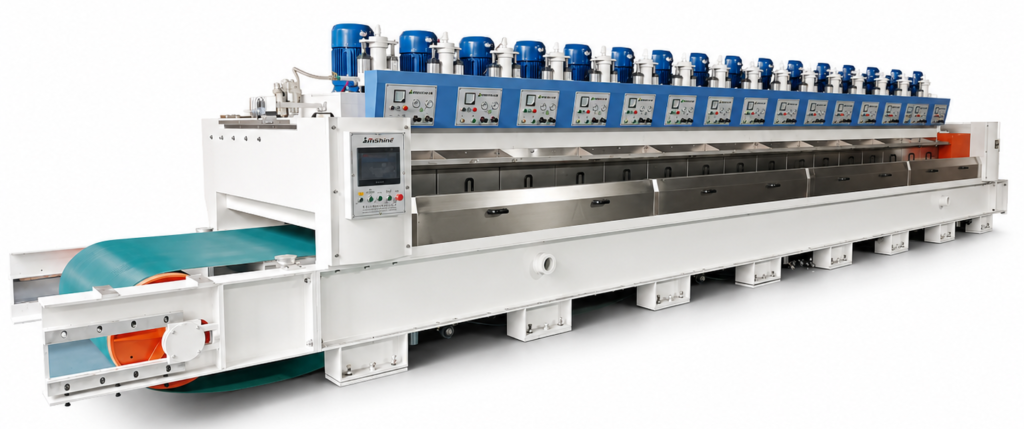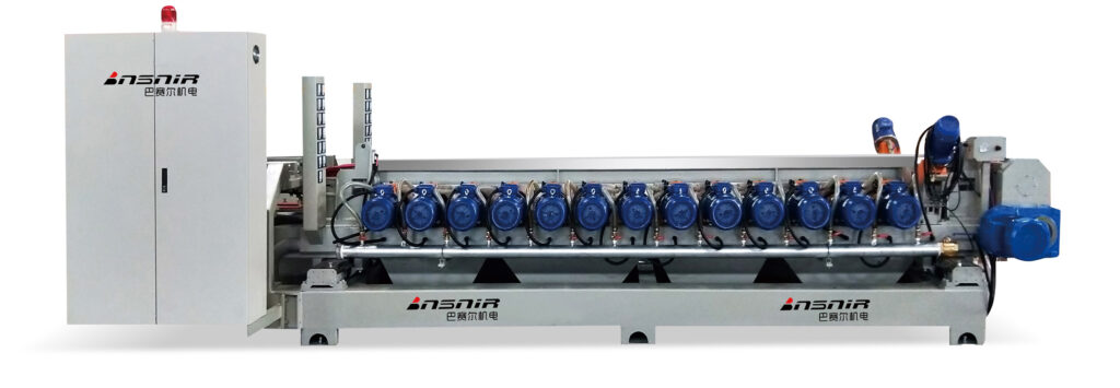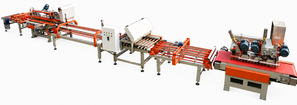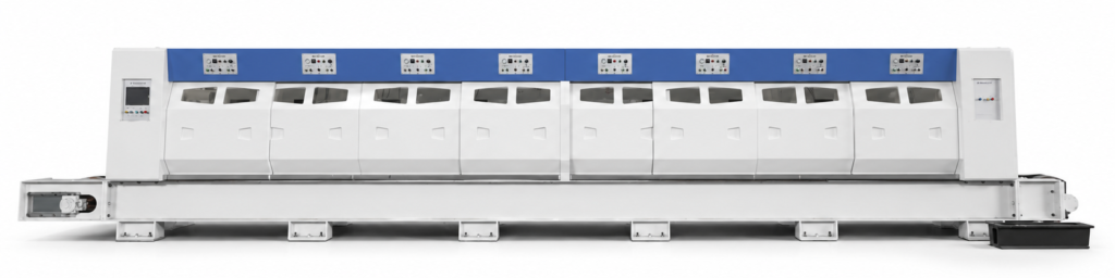
Lappato polishing on large-format slabs fails in ways that smaller-tile settings rarely expose. When production teams commission a 1200×2400 mm or 900×1800 mm line using parameters carried over from 600×600 mm tile runs, the result is often a mix of gloss banding, edge dullness, intermittent breakage, and surface contact loss—defects that appear inconsistently and can take days to trace back to support and flatness conditions rather than abrasive selection. The compounding problem is that the corrective instinct—reduce pressure, slow the line—protects slabs but introduces throughput loss and geometry-driven finish variation that can’t be resolved at the polishing head. The judgment that matters at start-up is whether the entire processing path, from incoming slab condition through polishing support to downstream handling, has been validated together under live production conditions before the format is approved for regular output.
Support Conditions Unique to Large Formats
Support design for large-format lappato polishing is not a scaled-up version of smaller tile support. The governing problem is that a longer unsupported span under polishing head pressure creates localized deflection, and that deflection directly redistributes stock removal across the slab surface. On smaller formats, the supported span is short enough that head contact remains stable through most of the polishing pass. On large slabs, even modest roller spacing misalignment or a single non-coplanar support element can produce a contact gradient that registers as a gloss band in the finished surface.
The following conditions should be evaluated as format-specific design criteria, not assumed to carry over from the existing line configuration.
| Support Condition | Why Large Formats Differ | What to Confirm |
|---|---|---|
| Support span length | Long unsupported sections increase deflection under head pressure | Verifying that support spacing limits slab deflection within acceptable range |
| Roller/support layout | Misalignment or non-coplanar supports cause tilting and uneven contact | Checking that all support elements are coplanar and stable across the working width |
| Dynamic head contact | Local deflection changes stock removal distribution | Confirming that head contact pattern remains consistent under polishing pressure |
| Edge support during polishing | Cantilever effect when edges are unsupported can raise edge stress | Verifying edge stabilisation and no lifting during head passage |
| Transfer support at infeed/outfeed | Entry and exit transitions can introduce instability or misalignment | Checking transfer platter alignment and slab support continuity at interfaces |
Edge support deserves particular attention. When the leading or trailing edge of a slab is unsupported at the moment the polishing head crosses it, the cantilever effect increases local bending stress at the edge zone. This is not always visible as immediate breakage—it can appear as micro-cracking or chipping that only surfaces after stacking or downstream handling. Transfer support at infeed and outfeed transitions introduces a related risk: if the entry platter and the polishing conveyor are not coplanar, the slab can enter with a slight tilt that persists through the polishing pass, creating asymmetrical head contact regardless of how well the polishing head itself is set.
Support plane validation should be treated as a format-specific commissioning step, not a one-time machine installation check.
The practical confirmation sequence is: verify roller and support coplanarity across the full working width before the first trial run, observe slab behaviour—looking for any lifting, rocking, or tilting—during head passage, and check whether the contact pattern is consistent along the full polishing span. None of these can be confirmed by machine documentation alone; they require observation under polishing conditions with the target slab format in place.
Incoming Flatness and Head Contact Variation
Incoming flatness deviation is the variable that most commonly creates systematic lappato finish problems on large formats that cannot be corrected by adjusting polishing parameters. A slab with edge curl, overall bow, twist, or a thickness wedge presents a changing contact geometry to the polishing head as it travels across the surface. The polishing head responds to what it physically contacts; it cannot distinguish between a surface that is being finished and a surface that is deflecting away from or into it.
The four principal flatness deviations each produce a distinct failure pattern.
| Incoming Flatness Deviation | Effect on Head Contact | Risk to Lappato Finish | What to Verify |
|---|---|---|---|
| Edge curl (kiln roll) | Gap at head contact near slab edges | Uneven edge gloss, increased edge stress, possible breakage | Incoming edge flatness tolerance and support compensation |
| Overall bow | Variable head pressure across slab surface | Gloss bands, localised over- or under-polishing | Bow deviation against the flatness limit for large formats |
| Twist | Intermittent or skewed contact along the head path | Gloss variation and potential vibration marks | Slab orientation and twist control before polishing |
| Thickness wedge | Gradual change in contact depth along polishing span | Asymmetrical stock removal, one side under-polished | Thickness uniformity and head height adjustment strategy |
The operational implication is that gloss defects caused by incoming flatness deviation are often diagnosed incorrectly as abrasive-selection problems or head-pressure problems, leading to parameter changes that do not resolve the root cause and may introduce new inconsistencies. Before adjusting polishing settings in response to uneven gloss, the inspection priority should be to measure incoming slab flatness on a representative sample and map which deviations correlate with where gloss variation appears on the finished surface.
ISO 10545-2 provides a useful testing framework for flatness measurement methodology, but its dimensional tolerances apply to finished tile products and should not be read as governing limits for incoming slab flatness before lappato polishing. The relevant flatness limit for pre-polishing slabs is a machine- and setup-dependent figure that should be defined during commissioning, not assumed from product standards.
Breakage Exposure Across the Polishing Span
Breakage during lappato polishing on large formats is a dynamic failure pattern, not a fixed-rate outcome. The probability of a breakage event at any point along the polishing pass is a function of three interacting variables: the unsupported span beneath the slab at that moment, the head pressure being applied, and any material flaw or flatness deviation that concentrates bending stress at a weak location. All three can change across a single pass.
The most damaging mistake is treating breakage as an acceptable background rate before the support and parameter configuration is properly validated. Breakage that appears random during early trials often has a repeatable spatial pattern—concentrated at mid-span, at the entry transition, or at the trailing edge—that points to a specific support gap or head-pressure setting. Identifying that pattern requires recording where on the slab each breakage occurs and correlating it with the support layout, not simply counting events and reducing pressure globally.
Breakage location pattern is more diagnostic than breakage rate during initial trials.
Reducing head pressure to manage breakage risk is a legitimate response, but it changes the stock removal profile and may leave geometry-driven surface variation that lighter passes cannot resolve. This is the core trade-off: the support and incoming flatness conditions determine how much pressure the slab can tolerate; the polishing requirement determines how much pressure the process needs. Where those two envelopes do not overlap adequately, the resolution is a support or flatness correction, not a further reduction in polishing intensity.
Any deflection limits or breakage thresholds used as design figures should be treated as machine- and format-specific planning criteria. They are not transferable across different machine configurations or slab thicknesses without re-validation.
Throughput Tradeoff from Gentler Processing
The decision to reduce line speed or head pressure in response to breakage or surface quality issues on large-format slabs has a direct throughput consequence that production teams often underestimate at start-up. Gentler processing parameters protect the slab but reduce output per shift. If the gentler settings also leave geometry-driven finish variation—gloss banding from bow, edge dullness from curl—then the throughput reduction does not fully resolve the quality problem either. The line runs slower and still produces inspection failures.
This trade-off should be quantified before it becomes a standing operating condition. The key question is whether the throughput reduction required to run safely is compatible with the production plan for the format. If it is not, the resolution is upstream: improving incoming flatness control, correcting support conditions, or adjusting the polishing sequence—not simply accepting a permanent speed reduction.
The practical boundary condition is that gentler processing parameters validated on one machine configuration may not produce equivalent results on a different line, even with the same slab format. Line speed, head pressure, abrasive sequence, and support layout interact together. Figures from integrator references or comparable installations are useful as starting points for commissioning, but the production-viable parameter set must be established on the actual line.
Throughput reduction should be treated as a provisional measure pending support and flatness correction, not as the final operating condition.
When process engineers are setting commissioning parameters for a large-format lappato line, the throughput consequence of the selected settings should be explicitly part of the sign-off discussion. A parameter set that achieves acceptable surface quality at a throughput that cannot meet production demand has not solved the problem; it has deferred it.
Interfaces with Washing and Downstream Handling
One of the more persistent sources of commissioning delay on large-format lappato lines is that polishing, washing, and downstream handling are procured and signed off as separate systems, with no single party owning the full support and transfer plane across all three. When a surface defect or breakage event appears after the polishing section, the root cause may be in the transfer to the washer, the washer-to-dryer transition, or the stacking equipment—but without integrated commissioning oversight, each equipment owner reviews their own section in isolation and the defect source remains unresolved.
Each interface point carries a specific risk profile that should be reviewed during commissioning, not assumed to be resolved by individual equipment specification.
| Interface Point | Potential Gap | Risk If Unaddressed | What to Confirm |
|---|---|---|---|
| Polishing to washer transfer | Speed mismatch, slab tilt, or water overflow | Surface scratching, water marks, slab jamming | Conveyor speed synchronisation and slab entry alignment |
| Washer to dryer transition | Water carryover or roller height offset | Inconsistent drying, re-wetting marks, possible contamination | Dryer entry clearance, water removal efficiency before drying |
| Downstream stacking/handling | Drop height, alignment, or accumulation speed | Edge chipping, breakage, scratches during stacking | Handling equipment settings, stacker alignment, and soft-contact elements |
| Post-polishing conveyor before washing | Accumulation delay or belt condition | Abrasive residue transfer, scratches, heat build-up on slabs | Conveyor belt condition and transition cleanliness |
The polishing-to-washer transfer is particularly vulnerable on large formats because speed mismatch or slab tilt at this transition can introduce surface scratching on a freshly polished lappato surface. The conveyor belt condition before washing also deserves inspection: abrasive residue or contamination on the belt transfers to the polished face and creates marks that are difficult to attribute to a specific station during later quality review.
The practical requirement at commissioning is that the full path from polishing exit to final stacking must be walked under load, with slabs inspected after each transition. Defects identified after stacking need to be traced back through each interface rather than assumed to originate at polishing. This requires coordinated inspection rather than section-by-section sign-off.
Format Approval on Representative Slabs
Format approval should not be based on laboratory data or parameter sheets from comparable installations. The condition that matters is whether representative slabs of the actual production body, at the intended production thickness, pass support, breakage, appearance, and transfer checks under live line conditions. Lab-prepared samples and commissioning-phase test pieces often do not replicate the incoming flatness variation, body homogeneity, and handling dynamics present in regular production. Approval based on those samples can leave critical failure modes undiscovered until a production batch fails.
The approval review should cover five distinct areas, each requiring its own evidence type and a defined owner.
| Approval Area | What to Check | Evidence Needed | Owner to Confirm |
|---|---|---|---|
| Support stability | Slab does not lift, tilt, or deflect excessively during polishing | Visual observation and support deflection assessment | Machine integrator/process owner |
| Head contact uniformity | No contact loss or pressure spikes across the slab | Lappato gloss uniformity map or contact indicator test | Quality/technical |
| Breakage rate | Acceptable breakage across a full-line trial | Breakage event count and root-cause record | Production/quality |
| Surface appearance | Consistent gloss level, no edge dullness or stripe patterns | Visual inspection under representative lighting | Quality |
| Transfer integrity | No handling damage through polishing, washing, and stacking | Inspection of slabs after each downstream step | Operator/QA |
The most common gap in format approval is skipping the transfer integrity check. Teams that inspect slabs immediately after polishing, find acceptable surface appearance, and sign off on the format without checking condition after washing and stacking frequently discover edge chipping or handling-induced marks in the first production batch. By that point, the root cause—stacker alignment, conveyor drop height, soft-contact element condition—requires a second commissioning intervention.
Surface appearance consistency and breakage rate during the trial run are practical review criteria whose acceptance levels need to be defined by the production and quality teams for the specific format and product specification. ISO 10545-2 can provide a testing framework for gloss measurement or dimensional verification as part of the review, but its dimensional limit values are not automatically applicable as large-format lappato slab approval thresholds. The acceptance criteria for this format must be agreed before the trial run begins, so that the evidence collected during the run supports a clear decision rather than a deferred one.
Format approval based on partial-line trials, without transfer integrity checks, routinely delays the production release decision.
For production teams planning a large-format lappato line or approving an additional format on an existing line, the sequence that reduces commissioning risk is: resolve support coplanarity and edge stabilisation before the first trial run; measure and record incoming flatness on representative slabs before attributing gloss defects to abrasive selection; establish where breakage events occur spatially before reducing pressure globally; quantify the throughput consequence of any gentler parameter set before accepting it as the operating condition; and inspect slabs through every downstream interface before signing off on format approval. Each of these steps requires observation under live production conditions, not document review alone.
The decision to release a large format for regular production is best supported by a structured trial that generates evidence across all five approval areas—support stability, head contact uniformity, breakage rate, surface appearance, and transfer integrity—with defined acceptance criteria agreed in advance and a single owner responsible for the full line path. Where those conditions have not been met, production release should be deferred rather than managed through ongoing parameter adjustment after the fact.
Frequently Asked Questions
Q: We already run a ceramic tile polishing line for smaller sizes. Can we simply add lappato abrasives and run large-format slabs?
A: No. Switching abrasives alone will not prevent gloss banding, edge stress, or breakage on large formats. The support plane, edge stabilisation, and transfer transitions must be re-validated for the larger unsupported span because local deflection under head pressure changes stock removal distribution in ways that abrasive selection cannot correct.
Q: What is the very first practical check we should perform before running trial slabs on a large-format lappato line?
A: Verify roller and support coplanarity across the full working width under load. Without a confirmed coplanar support plane, any finish variation or breakage data collected during the trial will be unreliable, and subsequent flatness or parameter adjustments will struggle to isolate the true root cause.
Q: Is there a standard flatness tolerance we can use to reject incoming slabs before lappato polishing?
A: There is no universal reject threshold. The acceptable flatness deviation for your line is machine- and format-specific, and must be defined during commissioning by correlating measured slab profiles (edge curl, bow, twist, wedge) with the resulting surface defects. Using general product standards like ISO 10545-2 limits will not predict lappato-contact behaviour on your equipment.
Q: Should we invest in a dedicated large-format lappato line or try to upgrade our existing polishing machine?
A: A dedicated line from a single integrator that designs the polishing, washing, and handling path together typically reduces commissioning risk because transfer interfaces are owned end-to-end. An upgrade is possible but requires extensive revalidation of support, edge entry, and downstream handling. Without that, format-approval delays and inter-section defects are more likely.
Q: Given the breakage and throughput risks, is large-format lappato polishing economically viable for a smaller manufacturer?
A: It can be, provided commissioning validates the full processing path so breakage is minimised and throughput reduction remains temporary. The hidden costs of gloss defects, micro-cracking, and repeated parameter adjustments on an improperly commissioned line can quickly erode the margin advantage that large-format products carry.