A squaring-line proposal can list wheel counts, positions, and tool names without ever explaining what each position is supposed to accomplish or how that work adds up to the tile the factory actually needs. Before a technical offer moves toward a trial or purchase order, the buyer has to be able to trace every position back to a duty, and every duty back to an output the factory can measure.
Define the Output Duties the Wheel Map Must Serve
A wheel map only means something once the factory has stated, in verifiable terms, what tile enters the line and what tile must leave it. That starts with the incoming tile range and its edge condition — whether tiles arrive already cut close to size or carry significant stock to remove, whether edges are clean or already chipped — because this determines how much work the sequence has to perform before it reaches any finishing duty. It continues with the outgoing requirements: length, width, side straightness, rectangularity, and surface condition, plus how the tile will interface with whatever comes after the squaring line, such as packing, sorting, or a further finishing stage.
ISO 10545-2 supports naming these as legitimate dimensional and surface-quality characteristics for ceramic tile. That is useful because it gives the buyer and supplier a shared vocabulary for what “correct” output means. It does not, however, supply a BASAIR tolerance or a project acceptance value. The standard defines what is measured and how it can be tested; it does not decide what the factory’s contract requires. That agreement — the actual tolerance, the sampling basis, and who measures it — has to be settled separately between the factory and the supplier.
This matters because the wheel map cannot be judged in isolation. A sequence that looks efficient on paper may be built around an incoming condition the factory does not actually have, or an outgoing tolerance tighter or looser than what the factory’s downstream process requires. If the incoming edge condition is inconsistent — mixed batches, variable pre-cut accuracy — the wheel map needs enough early-position capacity to normalize that variation before later positions can do finishing work reliably. If the outgoing requirement includes a surface characteristic, such as an edge appearance beyond plain squareness, that changes which positions are load-bearing for dimensional correction and which are reserved for a different purpose entirely.
The practical implication for the buyer is that the output duties should be written down and agreed before the wheel-by-wheel detail is reviewed. Without that reference point, there is no way to judge whether a given position is doing necessary work, redundant work, or work aimed at a specification the factory never confirmed.
Map Every Position to a Named Wheel Duty
Once the output duties are fixed, the proposal should convert them into a numbered, side-specific sequence — a wheel map the factory can walk through position by position rather than a general description of “squaring and chamfering stations.” For each position, the supplier should state the tool family proposed, the specific work assigned there, the condition the tile is expected to reach before moving to the next position, and whether that position is doing squaring work or is set aside for a distinct task such as chamfering.
| Proposal field | What the proposal must state | Decision boundary |
|---|---|---|
| Position identity | Sequence number, side, and physical location in the proposed line | The supplier must define the project-specific arrangement |
| Proposed tool family | The named wheel family assigned to the position | A family name alone does not prove compatibility or result |
| Assigned duty | The work assigned at that position and the condition passed to the next position | Duty and sequence require supplier explanation and project confirmation |
| Process context | Whether the position belongs to the proposed dry, wet, or other confirmed route | Route-specific interfaces and values must be stated by the supplier |
| Verification link | The agreed output characteristic, trial observation, or evidence used to check the duty | ISO 10545-2 names dimensional characteristics but sets no BASAIR acceptance value |
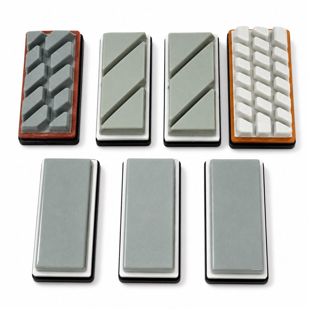
This level of detail matters because a tool family name carries no guarantee about the result at that position. BASAIR’s own documented distinctions between metal-bond, resin-bond, and chamfering-wheel families describe different tool categories, not a fixed order in which they must appear or a proof that a given family will perform a stated duty on the factory’s material. Likewise, ISO 6104 supports using unambiguous, traceable designation for rotating diamond tools in the schedule — so that “the wheel at position four” refers to a specific, identifiable product rather than a generic description — but the standard is a nomenclature framework, not a sequencing rule and not evidence of ceramic-tile compatibility.
A real architecture example illustrates why position-by-position detail cannot be assumed from a summary line-item count. The BMR TOP Squadra 12/1 Dry model uses multiple calibrating units on each side of the line. That is evidence that placing more than one calibrating unit per side is a legitimate architecture choice available in dry-squaring equipment generally — it demonstrates that unit count and position are attributes a design can specify. It does not establish what BASAIR’s proposed layout is, how many units a BASAIR line assigns per side, or what result that arrangement produces on the factory’s material. A competitor’s model confirms that an architecture pattern exists; it does not transfer as a claim about a different supplier’s line.
Where a factory’s material has more variable incoming geometry, the wheel map may need more positions doing corrective work before any finishing duty is reached, because each position can typically remove or correct a bounded amount of deviation. Where incoming geometry is already consistent, fewer corrective positions may be needed, freeing earlier positions for other work or allowing a shorter sequence. The map should show which case the proposal assumes, since the same wheel count can represent very different margins depending on what condition it is designed to correct.
Separate Dry and Wet Architecture Assumptions
The proposal needs to state plainly whether the line is dry, wet, or built around some other project-defined process, because this choice changes what the wheel positions depend on to function — not just how many positions exist. A dry-squaring architecture relies on its own process-support arrangement, dust or debris handling, and transfer interfaces between positions. A wet-squaring architecture depends instead on water supply, water removal, and cleaning at defined points in the sequence, and the transfer interface between positions has to account for wet tile handling rather than dry tile handling.
Where a dry-route reference point is used to illustrate a design idea, that architecture’s unit count, spacing, or control approach belongs to a dry-water-free process and cannot be assumed to carry over into a wet-route proposal, or vice versa. The presence of process-support and cleaning interfaces in one route does not tell the buyer what the equivalent interface requirement is in the other; each route has to state its own utilities, its own wheel specification suited to that route, its own speed and pressure assumptions, and its own expected wear behavior. None of these should be treated as portable between routes, and neither route should be assumed to be the generally preferable choice — the choice depends on the factory’s material, its existing line, and its downstream handling capability.
This separation also affects how the buyer reads compatibility claims. A tool or wheel family that performs a duty under dry conditions is operating under a different mechanical and thermal environment than the same family under wet conditions, because the presence of water changes cooling, debris clearance, and the load the tool experiences at the contact point. A proposal that names a tool family for a position without specifying which route that assignment assumes leaves an open question the factory cannot resolve by inspecting the tool name alone.
Where the factory already operates one route and is evaluating a shift to the other, the interface question becomes more concrete: the existing line’s transfer points, floor drainage or lack of it, and downstream handling were built around one route’s assumptions, and a proposal changing the route needs to state how those interfaces are affected, not just how the wheel positions differ.
Make the Proposal Verifiable Without Invented Guarantees
A wheel map earns credibility when each stated duty connects to something the factory can check — an agreed output characteristic, a trial observation, or evidence the supplier can produce — and when the proposal states who is responsible for confirming it. A duty stated without a verification link is an assertion, not a specification.
This is where the factory’s own project information becomes part of the process: the incoming tile range, the required outgoing characteristics, and the confirmed process route that the factory supplies are what allow a supplier such as BASAIR to configure a wheel map and prepare a quotation or trial plan around actual conditions rather than generic assumptions. Where that project information is incomplete or unconfirmed, the resulting proposal can only be provisional, and the wheel duties in it should be treated as draft assignments pending confirmation rather than settled commitments.
The proposal should also state its own exclusions and unresolved points rather than let the wheel count imply completeness. A sequence with a defined number of positions does not, by itself, establish throughput, tolerance achievement, finish quality, tool life, or acceptance — those outcomes depend on the confirmed material, the agreed process conditions, and the tooling actually supplied, and they need to be demonstrated through the agreed verification method rather than inferred from the architecture description. If a position’s duty is linked to a dimensional characteristic, the verification should reference the agreed measurement basis for that characteristic, consistent with how ISO 10545-2 frames dimensional and surface-quality testing, rather than an unstated assumption about what “acceptable” means.
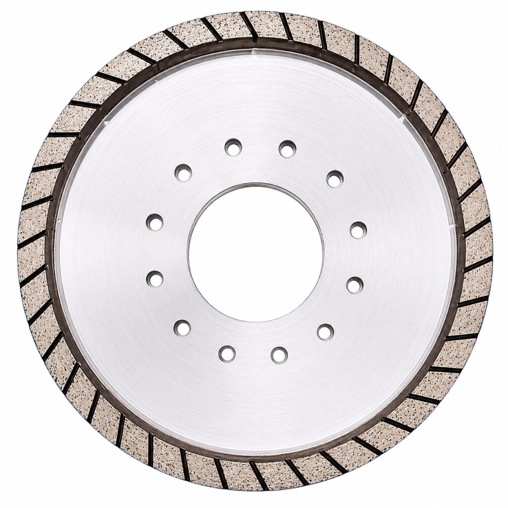
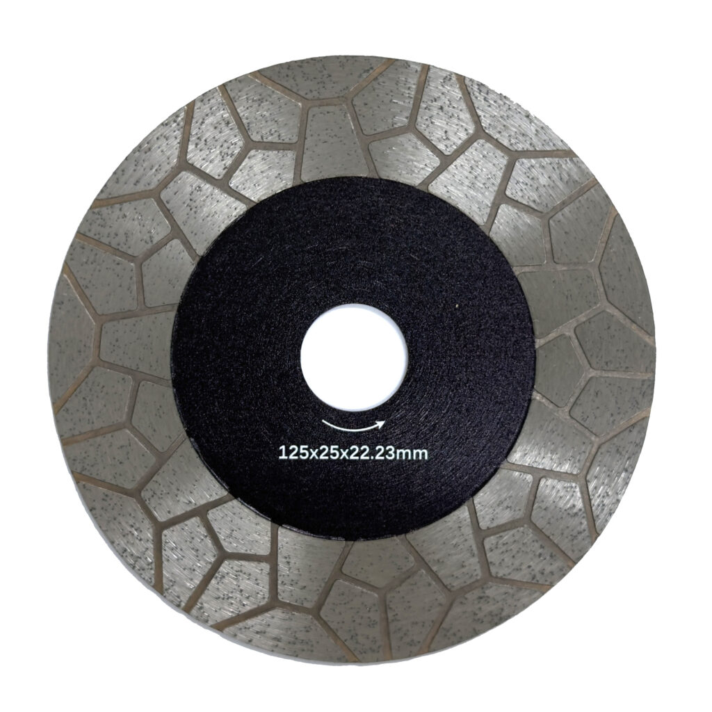
Where equipment such as the squaring and chamfering machine line or matched diamond squaring wheels is proposed for specific positions, the practical next step for the buyer is to request that each duty assignment be tied to the verification method and the party responsible for checking it, so that a revised technical offer or trial plan can be evaluated against confirmed criteria rather than against the wheel map’s apparent completeness alone.
Frequently Asked Questions
Q: Does a proposal with more wheel positions necessarily offer a better finished tile?
A: Wheel count alone does not establish the result. Review how each position serves your incoming tile range, required dimensions and edge condition, and downstream handoff, then ask for the evidence connecting its assigned duty to those requirements.
Q: What should we ask for if the quotation lists wheel families but no sequence?
A: Request a numbered, side-specific map in process order showing each wheel’s identity, assigned work, and condition passed to the next position. Have the supplier identify chamfering or other distinct edge duties explicitly so family names can be assessed within the proposed arrangement.
Q: Can we compare dry and wet proposals using the same wheel-count benchmark?
A: That benchmark does not establish equivalent duties or architecture. Confirm each proposal’s process route and its wheel map, process-support, cleaning, and transfer interfaces. Assess how each arrangement addresses the project requirement rather than importing a dry model’s unit count into a wet project.
Q: How can we check whether each proposed wheel duty is adequately explained?
A: Link it to an agreed output characteristic, trial observation, or supplier evidence and identify who confirms it. Require the proposal to show exclusions and unresolved tile or process data so unsupported assumptions remain visible before a revised offer or trial is requested.